Xóc đĩa online là một trò chơi cá cược được rất nhiều người chơi và hâm mộ. Hiện nay, trên mạng có nhiều nhà cái cung cấp trò chơi này. Dưới đây là bài viết chia sẻ về Top 10 Trang xóc đĩa online đẳng cấp số 1 Châu Á hiện nay mà bạn nên tham khảo ngay.
Xóc đĩa online là gì?
Xóc đĩa online là phiên bản chơi xóc đĩa thông qua mạng internet. Để tham gia vào trò chơi này, người chơi cần đăng ký tài khoản cá cược tại một nhà cái đáng tin cậy. Sau đó, họ có thể nạp tiền vào tài khoản và tham gia chơi xóc đĩa trực tuyến một cách dễ dàng và thuận tiện.
Luật chơi xóc đĩa trực tuyến không quá phức tạp, phù hợp cho người chơi mới tham gia hoặc có ít kinh nghiệm. Hơn nữa, tỷ lệ trả thưởng trong xóc đĩa trực tuyến cũng rất hấp dẫn. Điều này đã làm cho hình thức chơi này trở nên phổ biến và được nhiều người chơi yêu thích và lựa chọn để tham gia cá cược.
Trò chơi xóc đĩa trực tuyến mang lại sự tiện lợi và linh hoạt cho người chơi trong việc trải nghiệm trò chơi, cũng như cung cấp các khoản tiền thưởng và chương trình khuyến mãi hấp dẫn. Tuy nhiên, như với bất kỳ trò chơi đánh bạc nào, người chơi cần phải cẩn thận và lựa chọn những trang web casino trực tuyến uy tín.
Xóc đĩa online cavalrypilot là gì?
Cavalrypilot là website tổng hợp các nhà cái chơi xóc đĩa trực tuyến uy tín nhất trên thị trường hiện nay, cùng với đó là chia sẻ những kinh nghiệm cá cược online, hướng dẫn cách chơi xóc đĩa online đơn giản cho người mới, cách để nhận biết trang chơi xóc đĩa online uy tín cho anh em cược thủ.
Xóc đĩa online cavalrypilot đã nắm bắt được nhu cầu của người chơi và những niềm tin khi khách hàng chọn lựa và đặt cược tại các nhà cái xóc đĩa online. Vậy nên trong bài viết này, chúng tôi sẽ chia sẻ với các bạn Top 10 Trang xóc đĩa online đẳng cấp số 1 Châu Á hiện nay.
Trong bài viết này, cavalrypilot sẽ đưa ra những ưu nhược điểm của từng nhà cái để bạn có được cho mình những lựa chọn hoàn hảo nhất trên con đường khám phá và chiến thắng trong trò chơi xóc đĩa trực tuyến.
Tổng hợp 10 nhà cái xóc đĩa online uy tín nhất hiện nay
Nhận biết được nhu cầu người chơi online ngày càng tăng cao, vậy nên hiện nay có nhiều nhà cái cung cấp trò chơi xóc đĩa đổi thưởng. Bên cạnh đó, không phải kênh nào cũng hoàn toàn đáng tin cậy.
Nếu bạn không cân nhắc kỹ, rủi ro cao có thể gây ảnh hưởng đáng kể đến kinh tế cũng như cuộc sống của bạn. Dưới đây là 10 cái tên được đề xuất, giúp bạn lựa chọn một cách thoải mái mà không phải lo lắng về việc bị lừa đảo.
1. Rubik88 – Nhà cái xóc đĩa online uy tín số 1 hiện nay

Ưu điểm xóc đĩa rubik88
- Cung cấp bàn chơi xóc đĩa 3D với trí tuệ nhân tạo và bàn live với người thật.
- Đa dạng các phiên bản game cải tiến, với luật chơi mới lạ và mức thưởng hấp dẫn.
- Hệ thống giám sát bàn chơi xóc đĩa tự động và luật chơi chặt chẽ, đảm bảo tính công bằng cho tất cả các bên tham gia.
- Sảnh chơi đến từ những nhà phân phối hàng đầu như AG Gaming, King Master, đảm bảo tính trung lập.
- Trải nghiệm chơi trên ứng dụng cũng rất mượt mà.
Nhược điểm xóc đĩa rubik88
Rubik88 được đánh giá là một nhà cái chuyên nghiệp, tuy nhiên, hạn chế lớn nhất của họ là chưa cung cấp nhiều khuyến mãi đặc biệt dành riêng cho trò chơi xóc đĩa đổi thưởng.
2. Fun88 – Chuyên trang xóc đĩa online uy tín

Ưu điểm xóc đĩa fun88
Đầu tiên, Fun88 – nhà cái chính thức có đường truyền vô cùng mượt mà, ngay cả trên phiên bản di động. Nhà cái luôn quan tâm đến cách mang đến trải nghiệm tuyệt vời cho người chơi. Điều này làm cho chất lượng đường truyền trở thành một yếu tố quan trọng mà người chơi quan tâm. Do đó, tham gia vào Fun88 sẽ mang đến một trải nghiệm thực sự tuyệt vời.
Khi tham gia xóc đĩa tại nhà cái này, Fun88 cũng có những dịch vụ mà giúp họ giữ chân được người chơi, và đặc biệt ngày càng có nhiều người đăng ký tham gia, cụ thể như sau:
- Tất cả hoạt động kinh doanh và các bản game Xóc Đĩa được kiểm chứng bởi Curacao Gaming.
- Có sẵn nhiều bàn chơi Xóc Đĩa, từ phiên bản 3D cho đến bàn chơi với Dealer người thật.
- Mức đặt cược linh hoạt, đáp ứng được nhu cầu của đa dạng người chơi.
- Tỷ lệ trả thưởng hấp dẫn, và ngay sau khi ván cược kết thúc, người chơi có thể nhận được cộng thưởng.
Nhược điểm xóc đĩa Fun88
- Một điểm chưa được hoàn thiện của nhà cái là sự thiếu đa dạng trong danh sách casino/trò chơi. Người chơi có thể cảm thấy hạn chế khi muốn tham gia vào các trò chơi khác nhau.
- Fun88 có điểm mạnh là cung cấp khuyến mãi đặc biệt dành riêng cho Xóc Đĩa. Tuy nhiên, điều kiện để nhận khuyến mãi còn khá nghiêm ngặt và gắt gao.
- Thêm vào đó, việc rút tiền cũng gặp một số khó khăn. Người chơi cần phải xác minh tài khoản để thực hiện việc rút tiền nhiều lần.
3. W88 – Nhà cái xóc đĩa đổi thưởng luôn thu hút các xóc thủ
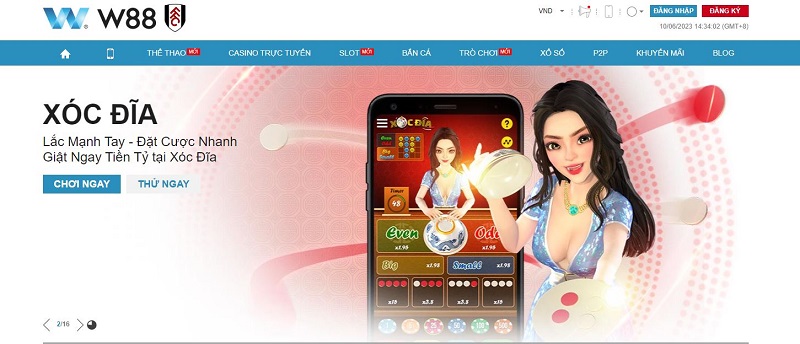
Ưu điểm xóc đĩa W88
- W88 là một nhà cái uy tín thu hút sự quan tâm của đông đảo người chơi với trò chơi xóc đĩa trực tuyến hấp dẫn.
- Giao dịch nạp và rút tiền tại W88 được thực hiện nhanh chóng, công khai, minh bạch và công bằng.
- Khi tham gia xóc đĩa tại W88 người chơi được nhận rất nhiều chương trình khuyến mãi và ưu đãi khủng
- Giao diện của W88 được thiết kế bắt mắt với nhiều hình ảnh, màu sắc và âm thanh sống động.
- Người chơi có thể tải ứng dụng W88 trên điện thoại di động để tham gia cá độ bất cứ khi nào.
Ngoài ra khi người chơi trải nghiệm xóc đĩa tại nhà cái này cũng hoàn toàn yên tâm với những dịch vụ được cung cấp như:
- Cung cấp sảnh chơi đa dạng, từ bàn ảo đến bàn chơi thật.
- Có bàn chơi thử cho phép người chơi trải nghiệm miễn phí.
- Luật chơi được công khai, với tỷ lệ cược hấp dẫn và nhiều cửa đặt thú vị.
- Các nhà cung cấp bàn chơi đến từ AG, SA, Playtech…
- Hình thức trả thưởng công bằng và minh bạch với tỷ lệ 1-1.
- Mức cược cao cho phép trải nghiệm xóc đĩa tại mức độ thách thức cao.
Nhược điểm xóc đĩa W88
- Trò chơi xóc đĩa tại nhà cái chưa được tối ưu hoàn hảo và hiệu quả nhất.
- Khi cần hỗ trợ, việc kết nối và đợi nhân viên hỗ trợ tốn khá nhiều thời gian, dẫn đến việc người chơi không nhận được tư vấn kịp thời.
- Mặc dù có nhiều chương trình khuyến mãi, tuy nhiên việc nhận được những ưu đãi này không phải lúc nào cũng dễ dàng.
4. M88 – Trang xóc đĩa đổi thưởng online xanh chín

Ưu điểm xóc đĩa M88
- Nhờ có thương hiệu lớn, Xóc Đĩa đổi thưởng online tại M88 đã được rất nhiều người chơi tin tưởng và lựa chọn.
- M88 cung cấp bàn cược xóc đĩa đẳng cấp quốc tế do SA, Bbin, SexyGaming và những nhà cung cấp khác đảm nhận.
- Giao diện của bàn chơi được tối ưu hóa, với tính năng đặt cược thông minh và dễ thao tác.
- Trải nghiệm xóc đĩa với những người chia bài thực tế, quyến rũ và cực kỳ hấp dẫn.
- Cầu xóc đĩa dễ dàng đoán được, mang lại những khoản tiền thưởng khổng lồ cho tất cả các thành viên.
- Đội ngũ CSKH của nhà cái tận tâm và rất nhiệt tình. Họ sẽ giải đáp bất cứ thắc mắc nào của người chơi một cách thỏa đáng.
- Nạp tiền và rút tiền nhanh chóng thông qua 5 ngân hàng lớn ở Việt Nam. Quá trình nạp, rút tiền chỉ diễn ra chưa đầy 5 phút
Nhược điểm xóc đĩa M88
Bên cạnh những ưu điểm đã được đề cập, nhà cái cũng tồn tại nhiều hạn chế.
- M88 thường bị phản ánh về các vụ lừa đảo trên mạng xã hội. Có người thậm chí tố cáo rằng họ đã bị mất tiền sau khi nạp vào tài khoản. Khi họ thắng và muốn rút tiền, lại gặp khó khăn và phải đợi lâu mới được xử lý.
- Khách hàng phản ánh về vấn đề này nhưng nhân viên tư vấn trả lời chung chung, không đủ thuyết phục. Đôi khi, tài khoản của khách hàng bị khóa một cách vô lý và họ không thể truy cập vào trang web.
- Trụ sở chính của nhà cái đặt ở nước ngoài, khiến việc khiếu nại và nhận phản hồi mất rất nhiều thời gian. Sự không ổn định của đường truyền cũng ảnh hưởng đến trải nghiệm chơi của khách hàng. Thỉnh thoảng, sự giật lag và bị ngắt kết nối khiến việc chơi trở nên khó chịu.
5. 188BET – Thiên đường xóc đĩa online sôi động
Ưu điểm xóc đĩa 188bet
- Phiên bản xóc đĩa truyền thống mang đến sự hấp dẫn và kịch tính cao, với những phần thưởng thú vị
- Bàn chơi 3D hoặc xóc đĩa online với người thật đều đảm bảo tính minh bạch, với nhiều mức cược khác nhau
- Nội dung giải trí ấn tượng đặc biệt có nhiều chương trình khuyến mãi đặc biệt dành riêng cho trò chơi Xóc Đĩa.
- Môi trường cá cược sôi động 188BET là một địa điểm lớn với nhiều thành viên tham xóc đĩa. Do đó, nhà cái chú trọng vào việc tạo môi trường kết nối người chơi và tổ chức các sự kiện để trao đổi kinh nghiệm và tạo sự gắn kết giữa các thành viên. Điều này tạo cơ hội cho người chơi mới học hỏi và kết bạn.
- Giao diện, hình ảnh, âm thanh đẳng cấp và chuyên nghiệp, với màu cam phối xám đơn giản, bố cục gọn gàng và hình ảnh sắc nét cùng âm thanh chất lượng cao. Nhờ đó, người chơi có thể thoải mái trải nghiệm trong thời gian dài.
- An toàn trong bảo mật: Với việc áp dụng bộ mã hóa 128 bit và hạ tầng MD5, 188BET đã chinh phục được lòng tin của cả những khách hàng khó tính nhất với chính sách bảo mật chặt chẽ và ngăn chặn việc đánh cắp dữ liệu.
Nhược điểm xóc đĩa 188bet
- Thường gặp tình trạng tắc nghẽn và lỗi link truy cập trong khung giờ quan trọng.
- Số lượng quảng cáo trong mỗi phần chơi cũng khá nhiều, đôi khi gây khó chịu cho người chơi.
6. Happyluke – Nhà cái đổi thưởng xóc đĩa online hấp dẫn

Ưu điểm xóc đĩa Happyluke
- Bàn chơi có phong cách hiện đại, tối ưu hóa các tính năng từ việc đặt cược đến việc nhận thưởng.
- Trả thưởng Xóc Đĩa online hấp dẫn, được xử lý nhanh chóng ngay sau khi trò chơi kết thúc. Có nhiều chương trình khuyến mãi hấp dẫn, được thiết kế đặc biệt cho trò chơi Xóc Đĩa.
- Sảnh chơi được cung cấp bởi những nhà phát hành nổi tiếng như Evolution, Palazzo…
- HappyLuke có giao diện đẹp mắt, âm thanh sống động và hình ảnh hấp dẫn. Sự kết hợp tinh tế giữa các tông màu chủ đạo như xanh, hồng và trắng tạo nên một nền tảng giao diện thu hút ngay từ cái nhìn đầu tiên.
- Các danh mục được hiển thị rõ ràng và đầy đủ, giúp người chơi dễ dàng thao tác mà không mất quá nhiều thời gian.
- HappyLuke cung cấp các phương thức giao dịch nạp và rút tiền thông qua tài khoản ngân hàng. Nhà cái hỗ trợ một loạt các ngân hàng lớn trong nước, đồng thời có hơn 100 giao dịch viên sẵn sàng hỗ trợ xét duyệt thanh toán một cách nhanh chóng và tiện lợi.
- Đội ngũ nhân viên chăm sóc khách hàng của HappyLuke được tuyển chọn và đào tạo kỹ càng. Họ trẻ trung, năng động và tài năng, sẵn sàng giúp đỡ và tư vấn cho khách hàng mọi lúc, mọi nơi. Thái độ vui vẻ, niềm nở và sẵn lòng giải đáp thắc mắc của họ giúp khách hàng cảm thấy được chăm sóc tốt.
Nhược điểm xóc đĩa Happyluke
- Thao tác trên app để chơi Xóc Đĩa vẫn còn chưa được mượt mà, đôi khi còn có hiện tượng giật, lag.
- Với số lượng sản phẩm cá cược đa dạng và việc cập nhật thường xuyên, HappyLuke có thể gây rối mắt đối với những người chơi mới không quen với các tựa game. Việc tìm kiếm tựa game yêu thích có thể gặp khó khăn cho những người chơi không quen thuộc.
7. FB88 – Nhà cái xóc đĩa trực tuyến uy tín số 1 hiện nay

Ưu điểm xóc đĩa Fb88
- Sảnh xóc đĩa quốc tế, chuyên nghiệp và đầy tiện ích từ các nhà cung cấp như Microgaming, Ebet, Skywind,…
- Trò chơi xóc đĩa trực tuyến được công khai rõ ràng, với hệ thống trả thưởng minh bạch.
- Số lượng bàn cược đa dạng, mang đến một không gian giải trí không giới hạn.
- Ngoài phiên bản chơi truyền thống, còn có nhiều phiên bản game xóc đĩa đổi thưởng cải tiến, luôn mang đến sự thú vị cho người chơi.
- Việc đăng ký tài khoản tại Fb88 nhanh chóng và dễ dàng.
- Quá trình nạp tiền diễn ra nhanh gọn.
- Fb88 hỗ trợ trên mọi nền tảng hoạt động như máy tính, điện thoại di động và máy tính bảng.
- Tỷ lệ cược tại Fb88 cao, mang lại cơ hội lớn cho người chơi.
- Bảo mật thông tin khách hàng tại Fb88 được đảm bảo tốt.
Nhược điểm xóc đĩa Fb88
- Giao diện xóc đĩa của FB88 được thiết kế rất chỉn chu, tuy nhiên so với phong cách truyền thống của phương Đông, có thể còn cách xa khỏi sự ưa thích của một số người chơi.
- Hạn mức rút tiền tại Fb88 khá thấp.
- Không hỗ trợ việc nạp tiền qua người thứ ba.
- Fb88 không chấp nhận thanh toán bằng Bitcoin hoặc tiền điện tử.
- Thương hiệu của Fb88 còn mới và chưa được khẳng định.
8. C88BET – Điểm đến xóc đĩa online đổi tiền đáng chơi nhất

Ưu điểm xóc đĩa C88bet
- Bàn chơi Xóc Đĩa trực tiếp hoặc 3D luôn sẵn sàng hỗ trợ người chơi 24/24.
- Tính năng đặt cược thông minh và thao tác dễ dàng giúp tránh sai sót trong quá trình chơi.
- C88BET hợp tác với các nhà cung cấp game xóc đĩa như GPI, Ebet, Evolution…
- Chương trình tặng 100k để khách hàng trải nghiệm thử xóc đĩa tại nhà cái này. Ngoài ra, còn cung cấp ứng dụng cho cả hệ điều hành iOS và Android và tặng thưởng ngay cho thành viên tải ứng dụng.
- Nhà cái này có một giao diện website nổi bật và sang trọng.
- Sở hữu ba giấy phép cá cược uy tín nhất.
- Dịch vụ khách hàng của họ thân thiện và sẵn sàng hỗ trợ 24/7.
- C88BET cung cấp một loạt trò chơi đa dạng và hấp dẫn.
Nhược điểm xóc đĩa C88bet
- Các điều kiện rút thưởng của chương trình khuyến mãi, đặc biệt là xóc đĩa có yêu cầu khá cao.
- Nhà cái này mới tham gia thị trường Việt Nam và còn non trẻ.
- Hiện tại, C88BET chưa cung cấp nhiều kênh liên hệ.
9. BK8 – Địa chỉ chơi xóc đĩa online cực đã

Ưu điểm xóc đĩa BK8
- BK8 đặc biệt chú trọng vào mảng xóc đĩa, do đó xóc đĩa có sẵn một số lượng lớn bàn chơi, nhiều phiên bản với cửa đặt thú vị, tỷ lệ đổi thưởng cao.
- Sảnh cược xóc đĩa được cung cấp bởi SA, AE, Bbin, SexyGaming…
- Về khuyến mãi BK8 cung cấp nhiều ưu đãi đặc biệt bao gồm chương trình chào mừng và các chương trình khuyến mãi đa dạng đang diễn ra.
- BK8 cung cấp nhiều tính năng đặc biệt như trực tiếp phát sóng, thống kê số liệu cược, công cụ cược trực tiếp, và nhiều tính năng khác, giúp bạn theo dõi và cải thiện trải nghiệm chơi của mình.
- Ứng dụng BK8 dễ dàng tải xuống và sử dụng, mang đến cho người dùng trải nghiệm tương tự phiên bản máy tính và có giao diện thân thiện.
Nhược điểm xóc đĩa BK8
- Mặc dù BK8 có nhiều ưu đãi hấp dẫn và đa dạng khi người chơi tham gia xóc đĩa tại đây, tuy nhiên hầu hết các ưu đãi này đều đi kèm với các điều khoản ràng buộc khá nghiêm ngặt.
- Phương thức thanh toán: BK8 không cung cấp đầy đủ các phương thức thanh toán phổ biến như PayPal, Apple/Google Pay hay Skrill.
10. Vwin – Sân chơi xóc đĩa đổi thưởng uy tín

Ưu điểm xóc đĩa Vwin
- Là một nhà cái xóc đĩa trực tuyến có danh tiếng uy tín, Vwin đã được công nhận bởi cả người chơi và các chuyên gia.
- Danh sách trò chơi xóc đĩa tại Vwin được lựa chọn kỹ lưỡng và được phân loại từ mới đến cũ.
- Bàn chơi Xóc Đĩa 3D cùng với đó là tính năng đặt cược thông minh giúp người chơi có những trải nghiệm tuyệt vời trong quá trình chơi.
- Trả thưởng Xóc Đĩa hấp dẫn, được xử lý nhanh chóng ngay sau khi trò chơi kết thúc.
- Vwin hỗ trợ nhiều ngôn ngữ, bao gồm Tiếng Việt và nhiều ngôn ngữ khác. Bên cạnh đó, Vwin cung cấp nhiều loại tiền tệ khác nhau để người chơi thực hiện các giao dịch.
- Đội ngũ tư vấn khách hàng của Vwin được đào tạo chu đáo và có kiến thức sẵn có. Dịch vụ khách hàng được cung cấp 24/7 liên tục.
- Vwin cung cấp hình thức nạp và rút tiền thuận tiện, nhanh chóng và có thể thực hiện từ nhà.
- Giao diện của Vwin hoạt động mượt mà trên tất cả trình duyệt Windows. Máy chủ ổn định của Vwin mang đến một môi trường cá cược casino hoàn hảo, không bao giờ gặp sự cố.
Nhược điểm xóc đĩa Vwin
- Một điểm hạn chế của Vwin hiện tại là giao diện chưa hỗ trợ tiếng Anh. Điều này gây khó khăn cho các thành viên đến từ các quốc gia Châu Âu khi truy cập vào trang web của nhà cái.
- Các chương trình khuyến mãi tại Vwin chưa đa dạng và không quá nhiều. Mặc dù tiền thưởng được cung cấp khá cao, thời hạn của mỗi chương trình khuyến mãi không kéo dài lâu.
Cách để nhận biết trang chơi xóc đĩa online uy tín
Trong thời gian gần đây, nhu cầu tham gia trò chơi trực tuyến, đặc biệt là trò chơi xóc đĩa, ngày càng tăng cao. Do đó, ngày càng xuất hiện nhiều trang web xóc đĩa. Điều này mang lại nhiều lựa chọn cho người chơi, nhưng đồng thời cũng gây khó khăn trong việc lựa chọn trang web xóc đĩa uy tín nhất.

Nếu bạn vẫn chưa biết chọn trang web xóc đĩa nào, bài viết dưới đây sẽ là sự lựa chọn tốt nhất. Khi tham gia chơi tại đây, bạn sẽ được hưởng nhiều ưu đãi và an tâm tuyệt đối.
Có giấy phép kinh doanh hợp pháp
Một trong những tiêu chí quan trọng nhất và đầu tiên là sự tồn tại của giấy phép kinh doanh hợp pháp. Một trang web chơi xóc đĩa trực tuyến uy tín sẽ sở hữu một giấy phép hoạt động rõ ràng và công khai thông tin liên quan đến nguồn gốc của nhà cái.
Giấy phép hoạt động này phải được cấp bởi các cơ quan hoặc tổ chức có thẩm quyền trong lĩnh vực hoạt động của casino trực tuyến.
Với tiêu chí này, chúng tôi sẽ giúp bạn tìm ra những nhà cái an toàn nhất trên thị trường, tránh xa những nhà cái “ma” không rõ nguồn gốc hoặc không có đủ năng lực.
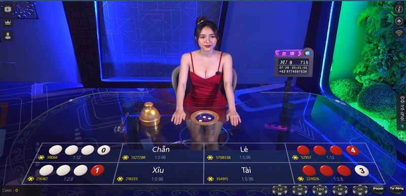
Quay hình trực tiếp với nhân viên chuyên nghiệp thật
Sự minh bạch và công bằng là những yếu tố mà bất kỳ người chơi nào cũng quan tâm khi tham gia cược xóc đĩa trực tuyến. Để đánh giá đúng tính chất công bằng và minh bạch, chúng tôi đặt ra một loạt câu hỏi như sau:
Liệu bàn cược có được phục vụ bởi nhân viên thật hay chỉ là nhân viên ảo? Có tính năng truyền hình trực tiếp và phóng to gần bàn cược hay không? Bộ dụng cụ xóc đĩa được lắc bởi tay người hay tự động?
Những câu hỏi này sẽ trả lời cho tính công bằng của một bàn cược. Không phải lời quảng cáo hoa mỹ mà chính những trải nghiệm trực tiếp mà chúng tôi cung cấp sẽ đưa ra câu trả lời cho bạn.
Tỷ lệ trả thưởng ở cả hai cửa chẵn và lẻ là từ 0.95 trở lên.
Tỷ lệ ăn cược hoặc trả thưởng là một yếu tố mà nhiều người chơi quan tâm. Yếu tố này có thể đánh giá được tính uy tín của một trang chơi xóc đĩa trực tuyến.
Tuy nhiên, các trang xóc đĩa uy tín sẽ có tỷ lệ trả thưởng hợp lý và cạnh tranh. Cùng số tiền đặt cược, nếu có nơi mang lại lợi nhuận cao hơn, thì chắc chắn đó là lựa chọn đúng, phải không?
Khuyến mãi xóc đĩa trực tuyến
Chương trình khuyến mãi là một tiêu chí quan trọng để đánh giá tính uy tín của một trang chơi xóc đĩa trực tuyến. Mục đích của các chương trình khuyến mãi là để tri ân người chơi và phát triển cộng đồng người chơi. Khuyến mãi không nên chỉ là lời hứa không thực tế hoặc không thể áp dụng hoặc quy đổi.
Các khuyến mãi như tiền cược miễn phí, thưởng nạp đầu sẽ được đánh giá cao hơn so với các chương trình hoàn trả tiền cược. Chúng tôi cũng sẽ đánh giá cụ thể về cách thức nhận khuyến mãi.
Tốc độ thanh toán tiền thưởng
Tốc độ thanh toán tiền thưởng khi người chơi thắng cược và độ dễ dàng khi người chơi muốn rút tiền thắng cược là một yếu tố quan trọng cần xem xét khi đánh giá tính uy tín của các nhà cái xóc đĩa.
Các nhà cái trực tuyến đều yêu cầu người chơi nạp tiền vào tài khoản để tham gia cá cược. Do đó, khi người chơi chiến thắng, các nhà cái cũng phải đảm bảo tốc độ rút tiền nhanh chóng và sự tiện lợi cần thiết.
Hỗ trợ ứng dụng di động cho chơi xóc đĩa trực tuyến
Vào năm 2023, cá cược trực tuyến và chơi xóc đĩa trực tuyến thông qua điện thoại di động đã trở thành xu hướng chung trên thị trường.
Vì vậy, người chơi cần những ứng dụng cá cược và hỗ trợ chuyên nghiệp cho các thiết bị di động của họ. Chỉ cần vài thao tác đơn giản, người chơi có thể đăng nhập vào tài khoản và tham gia chơi xóc đĩa trực tuyến bất cứ lúc nào, ở bất kỳ đâu.
Vì những lý do này, ứng dụng di động là một tiêu chí quan trọng khi đánh giá tính uy tín của một trang chơi xóc đĩa trực tuyến. Tiêu chí này cũng giúp đánh giá năng lực của nhà cái trong việc phát triển sản phẩm để đáp ứng nhu cầu ngày càng tăng của người chơi.
Trang web xóc đĩa uy tín phải thể hiện sự chuyên nghiệp và đáng tin cậy
Nếu nó là một nhà cái lớn, có tiếng và danh tiếng, thì chắc chắn sẽ luôn chú trọng đến uy tín và chất lượng của mình. Họ sẽ không gây ra bất kỳ vấn đề nào liên quan đến việc thanh toán tiền thưởng, đổi quà hay vi phạm các quy định.
Sự chuyên nghiệp được thể hiện qua nhiều khía cạnh, từ dịch vụ chăm sóc khách hàng đến các yếu tố trong trò chơi như hình ảnh và luật chơi… để trở thành một trong những trang web xóc đĩa uy tín và được nhiều người yêu thích.
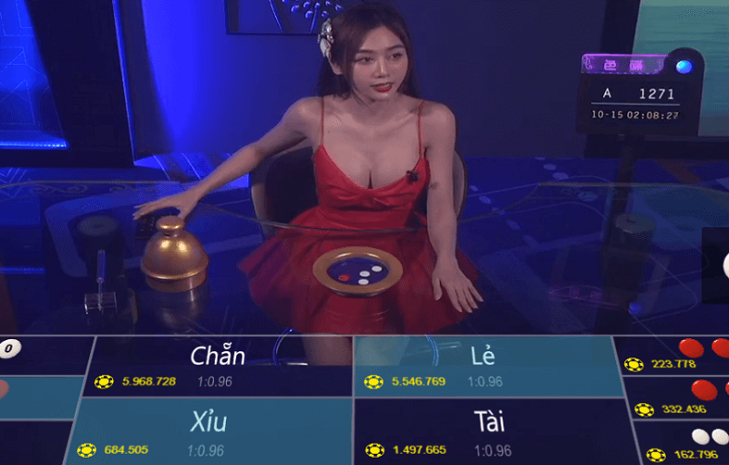
Các trang web xóc đĩa uy tín có hình ảnh đẹp và sống động
Khi chơi xóc đĩa trên một trang web uy tín, hệ thống sẽ truyền hình trực tiếp người chia bài từ các sòng bạc để người chơi có thể quan sát và tham gia đặt cược. Điều này mang đến cho người chơi cảm giác như đang tham gia vào một sòng bạc thực sự, tạo nên một trải nghiệm ấn tượng và mới mẻ.
Mọi chi tiết về hình ảnh và giao diện được đội ngũ kỹ thuật viên nghiên cứu kỹ lưỡng và tỉ mỉ. Mục tiêu của họ là tạo điều kiện thoải mái cho người chơi, không gây khó chịu khi quan sát qua điện thoại di động hoặc máy tính trong thời gian dài.
Các trang web xóc đĩa uy tín liên kết với nhiều ngân hàng
Trong việc chơi xóc đĩa đổi thưởng và rút tiền, việc nạp và rút tiền đóng vai trò quan trọng. Vì vậy, các trang web xóc đĩa uy tín thường hợp tác với nhiều ngân hàng lớn tại Việt Nam để giúp người chơi thực hiện các giao dịch thanh toán nhanh chóng nhất.
Hướng dẫn cách chơi xóc đĩa online đơn giản cho người mới
Để trở thành một cao thủ xóc đĩa và kiếm được tiền thật từ nhà cái, chúng ta cần hiểu rõ về các quy tắc và cách chơi cơ bản.
– Trước tiên, hãy nắm vững luật chơi cơ bản của xóc đĩa và các quy tắc quan trọng.
– Luật chơi xóc đĩa và các quy tắc cần ghi nhớ: Chơi xóc đĩa rất đơn giản. Đầu tiên, người chơi phải đặt cược trước khi bát xóc được mở.
Nhà cái sẽ đặt đồng xu vào bát và thực hiện quá trình xóc.
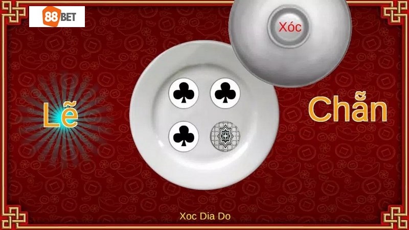
Người chơi cần dự đoán mặt của đồng xu khi bát được mở. Khi bát được mở, có nhiều trường hợp khác nhau có thể xảy ra:
Xóc đĩa với 1 đồng xu: Người chơi chọn mặt sấp hoặc mặt ngửa.
Xóc đĩa với 2 đồng xu: Có 3 lựa chọn cược, bao gồm cùng sấp, cùng ngửa và 1 sấp 1 ngửa.
Xóc đĩa với 4 đồng xu: Trong trường hợp này, có nhiều cách đặt cược khác nhau như chẵn/lẻ, theo màu sắc… Hiện nay, xóc đĩa với 4 đồng xu là phổ biến nhất, đặc biệt khi chơi trực tuyến. Người chơi sẽ được nhận thưởng nếu đoán đúng và sẽ mất số tiền đã cược nếu đoán sai. Dù chơi xóc đĩa trực tuyến hay theo cách truyền thống, luật chơi không thay đổi.
Bắt đầu bằng việc nghe tiếng xóc đĩa và đoán
Kết quả của một ván xóc đĩa không chỉ dựa vào việc rơi vào chẵn hoặc lẻ. Do đó, khả năng đoán trúng kết quả không chỉ đơn thuần là 50-50. Tính toán xác suất để đặt cược không phải là một công việc dễ dàng, vì vậy tại sao chúng ta không áp dụng một phương pháp khác?
Dù bạn đang chơi xóc đĩa truyền thống hay xóc đĩa trực tuyến, bạn có thể dễ dàng nghe tiếng các quân vị khi đang xóc. Hãy bắt đầu bằng việc nhận biết số lần xóc. Nghe nhiều lần, bạn có thể dựa vào sức mạnh của cú xóc từ người chia bài và quy tắc xóc để xác định cửa đặt nào là chính xác.
Bạn có thể chú ý rằng một số ván chơi sẽ tuân theo một quy luật nhất định. Ví dụ, nếu kết quả của ván trước là chẵn và người chia bài xóc 3 lần với tốc độ vừa phải và kết quả là lẻ, bạn có thể áp dụng quy luật này cho lần tiếp theo. Hầu hết các nhà cái sử dụng cùng một đồng xu, vì vậy việc nghe âm thanh và đoán được không quá khó khăn.
Đọc bảng vị để đoán kết quả
Bảng vị, còn được gọi là bảng chẵn lẻ, là một bảng hiển thị kết quả của các cửa cược trước đó. Dựa vào các số liệu trên bảng này, những cao thủ có thể dễ dàng lựa chọn cửa cược phù hợp cho ván tiếp theo. Đây cũng là một phương pháp chơi xóc đĩa thông minh mà các cao thủ thường áp dụng.
Để có được bảng vị, bạn cần sử dụng nhiều phương pháp chơi trong nhiều ván cược khác nhau.
Chọn một cửa và chơi gấp đôi
Gấp đôi là một phương pháp chơi phổ biến trong nhiều trò cá cược trực tuyến. Trong trường hợp của Xóc đĩa trực tuyến, bạn cũng có thể áp dụng phương pháp này để hạn chế rủi ro thua sau các ván cược. Đây là một cách chơi xóc đĩa thông minh để khôi phục vốn cược nhanh chóng, với các bước như sau:
Hãy chọn một cửa để đặt cược. Để chọn cửa phù hợp, bạn nên chú ý đến kết quả của các ván cược trước đó. Nếu thấy kết quả có hai lượt chẵn liên tiếp, đặt cược lẻ và nếu có hai lượt lẻ liên tiếp, đặt cược chẵn.
Sau đó bắt đầu đặt cược vào cửa này với một số tiền nhỏ ban đầu. Nếu thắng, bạn giữ nguyên số tiền cược cho ván tiếp theo. Trong trường hợp thua, bạn đặt số tiền gấp đôi so với ván trước.
Bật mí những kinh nghiệm chơi xóc đĩa online từ các cao thủ
Để chiến thắng khi chơi xóc đĩa tại các sòng bạc chuyên nghiệp, cần phải trang bị nhiều kỹ năng. Nếu bạn lựa chọn phương pháp chơi này, hãy chú ý những điểm sau đây.
Tâm lý ổn định
Một người luôn lo lắng và lo sợ thất bại, không thể đưa ra quyết định chính xác. Nhiều người đến chơi xóc đĩa khi gặp khó khăn về tài chính, nhưng thực tế lại ngược lại.
Chuyên gia cho rằng đây là lúc tâm lý không ổn định, và việc chơi xóc đĩa trong trạng thái này sẽ có tỷ lệ thua cao, còn được gọi là “dây đen”. Tâm lý tốt là yếu tố quan trọng nhất để bắt đầu thành công.
Có thể bạn chưa biết, khi chơi xóc đĩa online và đặt cược tiền thật, chúng ta đều trải qua một cuộc “tâm lý chiến”. Những người mới chơi thường có tâm lý không ổn định, không thể kiểm soát được những cảm xúc mạnh mẽ như sự hy vọng vào may mắn, lòng tham muốn gỡ lại tiền.
– Đừng quá quan trọng vấn đề thắng thua. Những người chơi với tư tưởng chơi để vui vẻ thường có tâm lý ổn định nhất. Áp lực thắng thua sẽ làm cho tâm lý của bạn bối rối và không thể tập trung suy nghĩ.
– Hãy kiên nhẫn và kỷ luật với các chiến lược đã đề ra khi chơi xóc đĩa ăn tiền thật. Đừng chơi xóc đĩa online một cách tự phát và ngẫu nhiên.
Đừng tỏ ra kiêu ngạo khi chiến thắng và đừng nản lòng khi thua cược. Thắng và thua là chuyện bình thường và bạn nên biết cách dừng lại sau mỗi lần thắng hoặc thua.
Không mang quá nhiều tiền
Xóc đĩa là một trò chơi đánh bạc, dễ khiến người chơi mất kiểm soát về tiền bạc. Nếu không may rơi vào “dây đen”, người chơi có thể cảm thấy muốn lấy lại nhưng lại gây thêm tổn thất nặng nề.
Đặt một ngưỡng vốn cho bản thân là cách để kiềm chế lòng tham. Hãy chia nguồn tiền thành nhiều phần để có cơ hội lấy lại những gì đã mất khi ta đủ bình tĩnh, tự tin và tâm trạng tốt.
Biết rõ luật chơi để trăm trận trăm thắng
Mỗi sòng bạc thường có những quy định riêng về trò chơi xóc đĩa.
Chúng ta cần nắm vững những quy định đó để không rơi vào thế bị động và tính toán sai các nước đi. Tốt nhất là hỏi kỹ nhân viên hoặc quản lý trước khi đặt cược để đảm bảo đã hiểu rõ luật chơi và phần thưởng.
Chọn nhà cái uy tín
Uy tín luôn đặt lên hàng đầu khi chọn địa điểm chơi xóc đĩa trực tuyến. Không có ý nghĩa gì nếu chúng ta chiến thắng nhưng không được trả thưởng công bằng.
Lời khuyên từ những người đã trải qua là nên chọn những nhà cái có nhiều người tham gia.
Chơi xóc đĩa online trên điện thoại – Xu hướng 4.0
Trong cuộc cách mạng công nghiệp 4.0, việc chơi xóc đĩa online không phải là một ngoại lệ. Chơi xóc đĩa trên điện thoại đang trở thành sự lựa chọn hàng đầu của nhiều người chơi nhờ tính tiện lợi, đơn giản và nhanh chóng.
Thông qua ứng dụng chơi xóc đĩa trực tuyến, bạn không cần phải đến sòng bạc xóc đĩa casino trực tiếp và không cần một chiếc máy tính để bàn nặng nề nữa. Chỉ với một chiếc điện thoại nhỏ gọn, bạn có thể tải xuống ứng dụng xóc đĩa trực tuyến và trải nghiệm đầy đủ các tính năng cá cược.
Vậy làm thế nào để chọn một ứng dụng chơi xóc đĩa online trên điện thoại tốt nhất cho người chơi Việt? Dưới đây là 5 đặc điểm mà một ứng dụng chơi xóc đĩa trực tuyến trên mạng cần phải có:
Đường truyền ổn định
Hình ảnh cần được truyền tải một cách rõ ràng, không bị giật hoặc lag. Tốt nhất là chọn một ứng dụng từ một nhà cái hỗ trợ nhiều góc quay, đặc biệt là có góc zoom cho phép xem cận cảnh bộ dụng cụ xóc đĩa.
Giao diện thân thiện
Một ứng dụng xóc đĩa trực tuyến tốt phải có giao diện dễ sử dụng cho người chơi. Bố cục các nút bấm phải giúp người chơi đặt cược một cách dễ dàng. Ngoài ra, các tính năng đi kèm cần được bố trí một cách hợp lý để người chơi có thể dễ dàng theo dõi.
Khả năng tương thích
Tất cả các nhà cái lớn đều phát triển ứng dụng của mình để tương thích với hai hệ điều hành phổ biến nhất là Android và iOS. Thiếu điều này sẽ không được chấp nhận đối với một nhà cái uy tín.
Dung lượng nhỏ gọn
Hãy chọn một ứng dụng có dung lượng phù hợp với thiết bị của bạn để tránh tình trạng giật, lag hoặc đóng ứng dụng khi đang chơi.
Đầy đủ tính năng
Một ứng dụng xóc đĩa trực tuyến hoàn chỉnh cần có đầy đủ sản phẩm và tính năng giống như phiên bản trên máy tính. Các tính năng cá cược cơ bản bao gồm khả năng đăng nhập dễ dàng và gửi/rút tiền nhanh chóng.
Hướng dẫn tải phần mềm hỗ trợ chơi xóc đĩa online từ các cao thủ
– Xóc đĩa online hiện nay đã trở thành một trò chơi kiếm tiền hấp dẫn tại nhiều nhà cái. Với thời gian mỗi ván chơi ngắn, người chơi có thể nhanh chóng vận động vốn và có thể thắng lợi hoặc cũng dễ dàng hòa vốn khi thua.
– Mặc dù có tiềm năng, tỷ lệ thắng cược trong trò xóc đĩa trực tuyến thường ở mức trung bình. Vì vậy, thay vì dựa vào may rủi, một số người chơi có kinh nghiệm lại áp dụng một phương pháp kiếm tiền táo bạo hơn và hiệu quả gấp bội. Đó chính là sử dụng phần mềm hỗ trợ hack game xóc đĩa online, giúp tăng khả năng thắng cược lên đến 99%.
– Phần mềm hack xóc đĩa online là một ứng dụng dành cho điện thoại hoặc máy tính, được thiết kế để gian lận trong các bàn chơi xóc đĩa trực tuyến.
– Công cụ hack xóc đĩa online này giúp người chơi dự đoán kết quả của một ván chơi xóc đĩa bằng cách xâm nhập vào hệ thống dữ liệu của nhà cái, lấy trộm thuật toán xóc đĩa online để đoán trúng kết quả cho người dùng.
- Bước 1: Tải phần mềm hack xóc đĩa online về điện thoại hoặc máy tính. Hiện nay, có nhiều ứng dụng hack game xóc đĩa online phiên bản miễn phí cho người chơi trải nghiệm.
- Bước 2: Đăng nhập vào ứng dụng, cung cấp các thông tin cơ bản và mã code UDID trên thiết bị bạn muốn hack.
- Bước 3: Truy cập vào sòng xóc đĩa và đặt cược như bình thường. Phần mềm hack game xóc đĩa online sẽ tự động hoạt động và cung cấp kết quả cho các ván cược sắp tới cho bạn.
Dưới đây là tất cả thông tin mà chúng tôi muốn gửi đến các bạn Top 10 trang xóc đĩa online đổi thưởng uy tín nhất 2023 và cũng chia sẻ về cách lựa chọn một nhà cái đáng tin cậy.
Mỗi nhà cái đều có ưu nhược điểm và đặc điểm mạnh riêng, tuy nhiên dựa trên kinh nghiệm cá cược của chúng tôi, chúng tôi tin rằng sẽ giúp bạn nhiều hơn trong việc lựa chọn một cách hợp lý.
Hy vọng rằng các bạn đã thu thập được nhiều thông tin hữu ích và đã biết được TOP 10 nhà cái uy tín hàng đầu. Hãy chọn một nhà cái mà bạn yêu thích và tham gia đặt cược ngay. Chúng tôi sẽ tiếp tục cập nhật những nhà cái mới nhất, công bằng và tuân thủ pháp luật. Hãy theo dõi để xem thêm các đánh giá có giá trị.
Chúc bạn có những phút giây vui vẻ và hãy đặt niềm tin vào mỗi lần cược, chắc chắn rằng bạn sẽ nhanh chóng giành thắng lợi.